
This project was our first firmware project written in Rust. Most firmware projects for embedded devices are written in C or C++. Just like our projects such as the Frogwatch vibration sensor. However, Rust is slowly gaining traction as a promising alternative as it has a few important advantages. The language has a built-in dependency manager: Cargo. It guarantees memory safety at compile time and it offers zero cost high level abstractions.
We were waiting for the right opportunity to dive in. And this project seemed simple and low risk enough that it was worth the extra time investment.
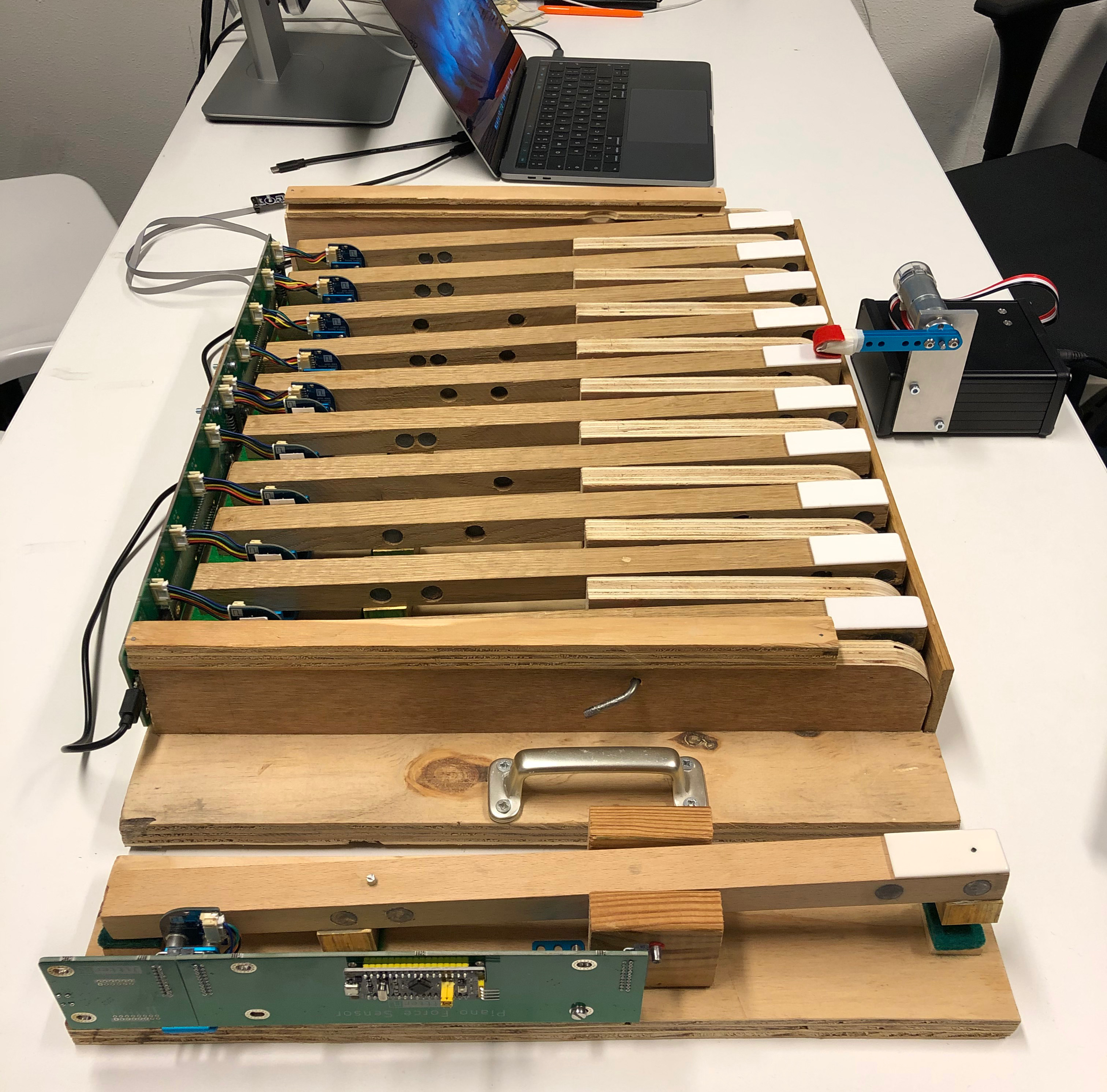
Piano technology is a discipline that studies piano mechanisms and their interaction with the pianist. For example one of the most important research areas is modelling piano actions to simulate a mechanical piano action with an electronic piano action. To investigate interactions between piano keys and pianists, we have installed an array of sensors in an experimental keyboard. The sensors are optical encoders aimed at measuring space-time behaviours of the keys when pushed by a pianist or by a robotic finger with different forces.
From a functional perspective the goal of the (embedded systems) project is:

Translate a signal from an optical encoder to something human readable and display it on a computer.
We will first describe the hardware part of the project for some context, but you can also jump directly to the code.


Even though we have mostly worked with NXP LPC microcontrollers before, for this project we picked the STM32F103. The STM32 microcontroller family seemed the most popular and best supported platform among Rustaceans. And the STM32F103 can be found on the (in)famous bluepill and blackpill boards that you can order on Aliexpress for less than the cost of a standalone STM32F103.
We selected the tiny AEDR-8300 optical encoder which has a resolution of 75 lines per inch. Its two outputs, A and B form a quadrature signal.
Finally the CP2102N IC will facilitate the UART to USB translation.
We decided to design a modular system. We needed to implement the sensors in two devices. In the first device we only need one optical encoder. In the second one we need to connect to ten encoders spread out over some distance to cover all ten piano keys for that tool. We decided to use the Dutch Polder Model and design a PCB that connects to up to five optical encoders, but make it daisy-chainable.

The mainboard houses one blackpil board that acts as the cpu. Measurement data will be send to the uart output connector. It will also listen to incomming transmissions on its uart input side and relay those messages to its output uart.
Additionally we designed a compatible uart->usb converter board that can connect to the same connector. This board will also supply the required. 3.3V and 5V power levels.
Checking if everything will fit together in a 3d model is always a good idea before ordering your boards.

Two weeks later we assembled the boards and fitted everything in real life.


Since this was our first Rust project we still had many concepts to learn. I cannot effectively learn a programming language from reading books, so rather I just start with a real project and figure it out on the go.
We tried to find some other embedded Rust projects on Github to see how they where approaching things. We noticed that many projects used the concurrency framework cortex-m-rtfm. I was intrigued by this framework and how it uses the Rust macro system to create this domain specific language to define real time apps. However, We wanted to try to build the firmware without these abstractions to better understand how things work on a lower level in Rust. This approach worked fine in the beginnnig when we were only interfacing with a single optical encoder.
Instead of going over the code line by line, We’d like to touch upon some concepts that were new to us.
The most fundamental thing when working with microcontrollers is writing bits to peripheral registers. Crates.io has these very convenient auto generated Peripheral Access Crates (PACs) that provide a nice API to interface with the registers. Since these crates are generated from the SVD files, they all work more or less similar. Something that’s rarely the case in C.
For example, configuring 10 pins for external interrupt to decode the quadrature encoder signals looks like this:
|
We write to registers using these closures.
There are two methods to write to the registers. We can use either write() or modify(). The differences is that modify performs an OR operation between the current register values and the new values in the closure, and write just writes the new value. So be careful that all the bits you do not explicitely set in the write closure will be zeroed.
For setting single bits there are usually methods available called set_bit() and clear_bit(). Those can be used immediately. When settings multiple bits using the bits(0b000) method, you need to use an unsafe{} block.
The decoding of the quadrature signals is done in interrupts. This means we need to access a few things in these interrupts.
EXTI peripheral to clear the interrupt and figure out which channel triggered the interruptThis is where things differ considerably from C. Since Rust will guarantee safe access to memory, we cannot just mark it volatile and access it in multiple ‘threads’. Interrupts at different priority levels can be considered different threads, but also the main loop which runs on the lowest priority is a thread. So if we want to share resources (read memory) between threads, we have to do it the Rust way.
By wrapping them in a globally available mutex we can access the data in both the main loop and interrupts. We have to do this for both the EXTI peripheral as the encoder state that we have encapsulated in the Encoder struct.
|
The types in Rust are very verbose and even the specific GPIO pins that will be used for this encoder are explicity part of the type. We also need RefCell and Option because the memory is intially empty and only initialized in main().
Now we can use access these objects in multiple contexts with the caveat that it needs to be accessed within a critical section (interrupt free section) cortex_m::interrupt::free. This is enforced by the mutex that requires a parameter _cs: &'cs CriticalSection that can only be created in such a section. That is how we can be sure that we will not be interrupted by a higher level thread and thus can modify this memory safely.
|
This still looks manageable, yet, when we add support for five encoders and also keep time using a timer interrupt and blink a LED, our list of globals will look like this:
|
This is quickly becomming ugly. You would think you can just put these encoders in an array. However they have different types since they are not using the same GPIO pins. And if you put them in a tuple, you will still need to type out the full types.
Turns out that cortex-m-rtfm is designed to hide all this boilerplate code. I am not sure if there is a better or cleaner way to do this without the RTFM framework.
Rust has zero cost abstractions. That means you can work on a relativley high abstraction level without hurting performance.
What we found out the hard way, is that this is only true if you turn on compiler optimizations (which makes sense of course). This is the case for both cpu cycles as memory usage.
Without optimizations on, the stm32f103 struggles to keep up with high uart baudrates. Especially since it does not have a FIFO buffer.
We also found out that we quickly run out of memory when we were adding buffers for the additional encoders.
For example, consider the following two examples. The first one consumes twice as much stack memory if you do not enable optimizations.
|
|
So to turn on optimizations during development you can add the following section to your Cargo.toml
|
Besides getting used to the general Rust syntax, these were the issues that cost us the most time to figure out or debug. In the end we rewrote the firmware using the cortex-m-rtfm framework to get rid of all the boiler plate. It also allows for easier management of priorities and resources for all the different threads/interrupts. The full code can be found on Github.
The most interesting thing about Rust so far is that once you’re done fighting with the compiler it mostly just works. Also working with a proper dependency manager is like a breath of fresh air.
The final component of the project is a python app using pyside2 and pyserial to log, visualize and analyze the encoder data.


